A skilled fabricator can build a good assembly on a flat bench with a tape measure, square and clamps. The challenge is building the same assembly repeatedly without losing time or allowing small errors to accumulate. This is where jigs and fixtures become valuable.
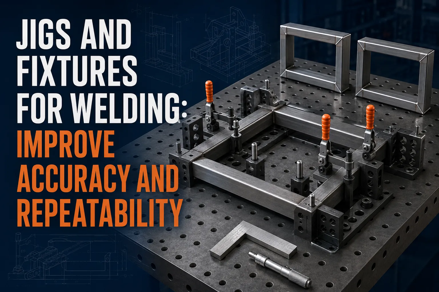
A well-designed fixture locates parts, holds them securely and gives the welder access to the joints. It turns repeated measurement into a controlled setup. The result can be faster production, more consistent dimensions and fewer parts rejected during final inspection.
Fixtures do not replace good drawings, qualified welding procedures or inspection. They make those requirements easier to achieve consistently.
Jig or Fixture: What Is the Difference?
The terms are often used interchangeably in fabrication shops. In general, a fixture supports and locates the work, while a jig may also guide a tool. For most welded products, “welding fixture” is the more accurate term, but the practical purpose is the same: control the relationship between components during assembly.
Common examples include:
- stops that locate tube or angle;
- pins that align holes;
- blocks that set a gap;
- nests that support curved parts;
- clamps that hold components against reference surfaces; and
- rotating frames that position the assembly for welding.
Even a simple angle stop bolted to a table can be a useful fixture.
Start with the Finished Assembly
Before designing a fixture, study the drawing and identify the dimensions that determine function. These may include overall width, mounting-hole position, diagonal equality, hinge alignment or the relationship between mating surfaces.
Choose fixture references that match the drawing datums wherever possible. If the product is installed from its bottom face, that face is often a logical primary reference. A side face can establish direction, while a stop can locate length.
Avoid locating every part from rough edges that may vary. Reference stable, repeatable features. A fixture that controls irrelevant dimensions while allowing a critical hole pattern to float will not solve the real problem.
Use the 3-2-1 Locating Principle
The 3-2-1 principle is a useful starting point for rigid parts. Three contact points establish a primary plane, two establish a secondary plane, and one establishes the final direction. Together they constrain movement without unnecessarily over-locating the component.
In practical fabrication, the contacts may be table surfaces, hardened buttons, pins or machined stops. The exact arrangement depends on the part, but the lesson is universal: locate the work deliberately.
Over-constraining can make loading difficult, especially when cut parts have normal dimensional variation. If every edge is trapped tightly, a slightly oversize blank may not fit. Provide relief where it does not affect function and control only the necessary features.
Design for Fast Loading and Unloading
A fixture saves time only if operators can use it efficiently. Plan the loading sequence before finalizing the design.
Ask:
- Can each component be inserted without twisting around clamps?
- Are the stops visible?
- Can the operator confirm that the part is fully seated?
- Are clamps reachable while wearing gloves?
- Can the welded assembly be removed after shrinkage?
- Will spatter trap the product in the fixture?
Toggle clamps, swing clamps, quick-release pins and simple wedges can reduce setup time. However, the fastest clamp is not always the best. It must apply force in a direction that seats the part against its locators.
Allow Access for Welding
Fixture designers sometimes focus on perfect restraint and leave no room for the torch, electrode holder or welding gun. Mark every weld on the assembly model and check access at the intended work angle.
Leave space for:
- the torch body and nozzle;
- the operator’s hands and protective equipment;
- tack welding;
- cleaning between passes;
- inspection; and
- grinding or finishing, when required.
Copper backing or removable support bars may be appropriate for certain joints, but their use must match the welding procedure and material. Do not add backing simply because it is convenient.
Plan for Heat and Distortion
A fixture can restrain movement during welding, but restraint does not remove shrinkage. Excessive restraint may transfer stress into the assembly or cause the part to spring after release.
Control distortion through the entire plan:
- use balanced joint design where possible;
- minimize unnecessary weld volume;
- tack in a controlled sequence;
- alternate weld locations;
- use skip or back-step techniques when appropriate;
- allow cooling between stages; and
- verify dimensions before completing all welds.
The fixture should support the intended sequence. Removable clamps can let the operator release or reposition restraint at defined stages. For a detailed discussion of shrinkage, see TWI’s guidance on distortion control.
Choose Suitable Fixture Materials
Mild steel is common because it is economical, weldable and easy to modify. Precision location points may benefit from machined or hardened components. Aluminium fixture parts can reduce weight but require attention to wear and heat. Copper is sometimes used near weld zones because of its thermal and electrical properties.
Consider:
- expected production quantity;
- part weight;
- welding heat;
- spatter exposure;
- required accuracy;
- wear at contact points; and
- whether the fixture must be portable.
Protect important reference surfaces from weld spatter. Replaceable wear pads and locating pins can extend fixture life. Avoid coatings or contaminants near welding that could create fumes or interfere with the process.
Build Adjustment into Early Fixtures
The first fixture for a new product should allow controlled adjustment. Slotted mounting holes, shim packs or bolt-on stops make it easier to correct the setup after a trial assembly.
Do not leave everything loose. Adjustment should be measurable and lockable. Once trials confirm the correct position, record the settings and, where appropriate, add dowel pins or fixed stops for repeatability.
A prototype fixture can be simple. The production version should incorporate lessons from loading, welding, inspection and maintenance.
Make Error-Proofing Visible
Good fixtures make incorrect assembly difficult. This is sometimes called poka-yoke or mistake-proofing.
Examples include:
- asymmetric pins that allow only the correct orientation;
- a stop that distinguishes left-hand from right-hand parts;
- colour-coded locations;
- engraved part identifiers;
- a gauge that confirms the correct component length; and
- sensors in automated or high-volume systems.
Visual confirmation is valuable. An operator should be able to see whether a part is seated against its stop rather than trusting an invisible contact.
Inspect the Fixture, Not Only the Product
Fixtures wear, bend and accumulate spatter. A product can drift out of tolerance even when the operator follows the normal process.
Create a fixture maintenance routine that checks:
- locator position;
- pin diameter and wear;
- clamp force;
- table flatness;
- loose fasteners;
- cracked welds;
- damaged threads; and
- buildup on seating surfaces.
Use a master part, checking gauge or periodic dimensional inspection to verify the fixture. Mark it with an identification number and revision so that the shop knows which product drawing it supports.
Safety Must Be Designed In
Fixtures must not create pinch points, unstable loads or awkward lifting. Heavy assemblies may need hoists, lifting points or positioners. Clamps should not release unexpectedly, and rotating fixtures require secure locks.
Keep welding leads away from sharp edges and moving mechanisms. Ensure the welding current has a reliable return path suitable for the process. Follow applicable ventilation, fire-prevention and personal protective equipment requirements. OSHA’s welding, cutting and brazing resources provide a useful safety reference, but local rules and site procedures also apply.
A Practical Fixture Design Checklist
Before releasing a fixture, confirm that it:
- references the product’s functional datums;
- controls critical dimensions;
- accepts normal cut-part variation;
- loads and unloads without interference;
- seats parts visibly against locators;
- provides access to every weld;
- supports the planned welding sequence;
- allows the assembly to shrink and release;
- protects reference surfaces from spatter;
- is stable under the full product weight;
- can be inspected and maintained; and
- has clear identification and revision control.
Final Thoughts
The best welding fixture is not necessarily the most complicated. It is the one that controls the correct features, supports the actual production sequence and remains easy to use.
Start with the drawing, define the datums and critical dimensions, then build only as much control as the process needs. Trial the fixture with real components, measure the result and refine it. This disciplined approach turns fixtures into production tools that reduce setup time, improve fit-up and make quality repeatable.

 No products in the cart.