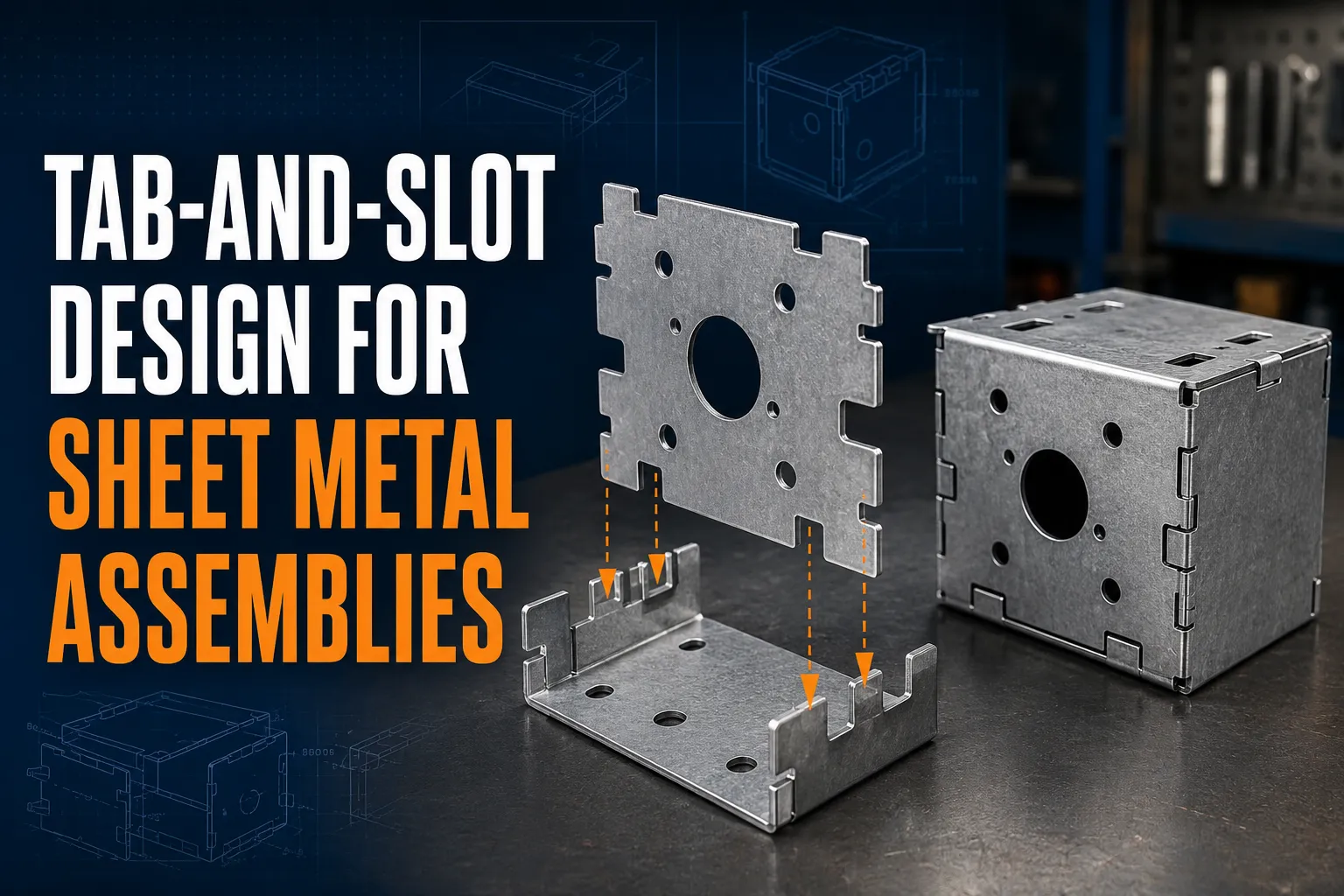
Tab-and-slot features can transform a collection of flat cut parts into a self-locating assembly. Tabs on one component engage slots in another, establishing position before welding or fastening. Used well, they reduce measuring, simplify fixturing and make assembly more repeatable.
Used poorly, the same features create parts that will not fit, tabs that break during handling or joints that cannot be welded properly. Successful tab-and-slot design requires more than drawing matching rectangles. The designer must account for the cutting process, material thickness, coating, bending and assembly sequence.
Why Use Tabs and Slots?
Tabs and slots are especially useful in laser-, plasma- or waterjet-cut fabrications such as:
- equipment enclosures;
- furniture frames;
- brackets;
- fire pits and grills;
- machine guards;
- carts and racks;
- decorative products; and
- prototype assemblies.
They can provide several benefits:
- rapid part location;
- reduced dependence on measuring tools;
- fewer or simpler external fixtures;
- improved squareness;
- easier identification of mating parts;
- controlled weld gaps; and
- faster dry assembly before permanent joining.
These benefits are strongest when the features are tied to functional datums and the design has been tested with the intended process.
Begin with Real Material Thickness
Sheet and plate are sold at nominal thicknesses, but actual thickness can vary by material, product standard and supplier. A slot designed exactly at the nominal thickness may be loose on one batch and impossible to assemble on another.
Measure representative stock or obtain the relevant supplier tolerance. Then define a slot width that includes intentional clearance for:
- actual material thickness;
- cutting-process variation;
- burr or dross;
- edge taper;
- surface coating;
- required assembly force; and
- thermal distortion during cutting.
There is no universal clearance value. A precision laser-cut stainless assembly and a thick plasma-cut mild-steel product need different allowances. Run a small coupon test before releasing a large production nest.
Understand Kerf Compensation
Kerf is the width of material removed by the cutting process. CNC software normally offsets the toolpath so the finished geometry approaches the programmed size. However, the actual result depends on machine calibration, consumables, gas selection, material condition and cutting direction.
Designers should normally provide finished part geometry, not manually distorted outlines that imitate kerf compensation, unless the cutting supplier specifically requests otherwise. The machine programmer can then apply the correct process compensation.
When purchasing cut parts, communicate whether slot dimensions are finished sizes and ask about achievable tolerance. A fit that depends on a few hundredths of a millimetre may not be realistic for every machine and thickness.
Select the Intended Type of Fit
Define what the tab is supposed to do.
Slip fit
The tab enters easily by hand and permits rapid assembly. This is suitable for welded products where clamps or tack welds will hold the final position.
Locational fit
Clearance is smaller so the feature controls alignment more closely. It can improve repeatability but is more sensitive to burrs, coatings and process variation.
Interference or press fit
The tab is intentionally larger than the slot or uses barbs to resist removal. This can be useful for specific products, but it demands proven machine capability and may distort thin sheets. It should not be assumed to replace structural joining.
State the intended fit in manufacturing information and validate it through samples.
Design Strong Tabs
A narrow tab cut from thin sheet can bend or break before assembly. Avoid making tabs unnecessarily long or slender. Where practical:
- use a generous root width;
- add a small internal radius at stress concentrations;
- keep the tab short enough to resist bending;
- avoid locating the root directly in a highly stressed region; and
- protect exposed tabs during transport.
The end shape affects assembly. Chamfered or rounded corners can help a tab find the slot, particularly when parts are assembled at an angle. Do not add tiny radii that the cutting process cannot reproduce reliably.
Provide Relief at Slot Ends
Internal corners created by cutting have a process-dependent radius. If a square-ended tab must sit fully at the end of a slot, corner interference can prevent proper seating.
Possible solutions include:
- rounding or chamfering the tab corners;
- adding dog-bone reliefs;
- extending the slot beyond the contact area; or
- accepting a designed stand-off.
Relief must not weaken the joint or create an unwanted visible opening. Review the final appearance and weld requirements before choosing the detail.
Use Tabs to Control the Correct Direction
A tab may locate a part along one axis while allowing adjustment along another. This is often better than locking every direction tightly.
For example, two round-ended tabs can locate a panel vertically while elongated slots permit thermal movement or assembly adjustment. One feature can establish the primary position and another can control rotation without over-constraining the part.
Think about tolerance stack-up. If several parts are each locked by tight tabs, normal variation can accumulate until the last component will not fit. Use a consistent datum strategy and add clearance or adjustment at non-critical interfaces.
Account for Bends
Tabs positioned near bend lines require careful planning. Bending changes geometry because material stretches and compresses through the bend region. A feature placed using the wrong flat-pattern assumptions can move after forming.
Check:
- bend allowance or bend deduction;
- inside bend radius;
- K-factor or validated bend table;
- grain direction where relevant;
- minimum feature-to-bend distance;
- tool access; and
- possible deformation of nearby slots.
Use the fabricator’s proven bend data rather than assuming the CAD default matches the press brake. SOLIDWORKS explains how bend tables relate flat length to material, radius and angle, while actual values still need to reflect the shop’s tools and process.
Plan the Assembly Sequence
A digital model can show all parts in place without proving that they can physically get there. Perform a step-by-step assembly review.
Ask:
- Which part is installed first?
- Does a tab need to enter straight or rotate into position?
- Will an earlier panel block a later part?
- Can the operator reach the joint for tacking?
- Can a damaged component be replaced?
- Does welding shrinkage trap a removable panel?
If multiple tabs must engage simultaneously, add lead-in clearance or install the part before adjacent panels. Exploded views and numbered components make the sequence easier to communicate.
Preserve Welding Access
Tabs can locate a joint, but they should not obstruct welding. Determine whether tabs will be:
- hidden inside the assembly;
- plug welded;
- fillet welded at the slot;
- ground flush; or
- retained only for location while another joint carries the load.
Do not assume a tab-and-slot connection has adequate structural capacity without engineering. The required weld size, length and quality must follow the drawing, qualified procedure and applicable code.
Avoid narrow cavities that trap fumes or make cleaning impossible. Provide drainage and venting where sealed sections, galvanizing or outdoor service demand it.
Consider Surface Finish and Coating
Powder coating, paint and galvanizing add thickness. A bare-metal slip fit can become too tight after coating. Decide whether parts will be assembled before or after finishing.
For welded products, assembly normally occurs before final coating, but mating features may still carry primer, scale or plating. For removable panels, allow coating clearance and avoid sharp edges that scrape the finish.
If the product will be hot-dip galvanized, consult the galvanizer early regarding venting, drainage and overlapping surfaces. The American Galvanizers Association provides design guidance, but project-specific review remains important.
Make the DXF Production-Ready
Every flat pattern should contain clean, closed geometry at the correct scale. Before export:
- remove duplicate and overlapping lines;
- convert splines when the supplier requires arcs or polylines;
- separate cut lines from bend or engraving marks;
- remove drawing borders and dimensions from cut layers;
- confirm units;
- identify material and thickness;
- confirm quantity and revision; and
- compare the exported DXF with the source model.
Do not combine multiple thicknesses in an unidentified file. Clear naming prevents the correct geometry from being cut from the wrong stock.
Prototype with a Clearance Coupon
Before cutting a complete assembly, create a small test coupon containing several slot widths, tab shapes and corner treatments. Cut it from the actual material on the intended machine and record which fit works best.
Repeat the test when changing:
- thickness;
- alloy;
- cutting process;
- supplier;
- coating condition; or
- critical machine parameters.
This inexpensive step is one of the most reliable ways to avoid a full sheet of unusable parts.
Tab-and-Slot Design Checklist
Before release, confirm that:
- actual material thickness has been considered;
- the cutting supplier understands finished dimensions;
- slot clearance matches the intended fit;
- tab roots are strong enough for handling;
- corners have suitable relief;
- critical features use consistent datums;
- the design is not over-constrained;
- bends use validated flat-pattern data;
- all parts can be assembled in a practical order;
- welding and inspection remain accessible;
- coatings have been considered;
- DXF geometry is clean and correctly scaled; and
- a process-specific coupon has verified the fit.
Final Thoughts
Tab-and-slot construction is powerful because it moves part of the assembly logic into the cut geometry. The best designs are not merely self-locating on screen; they tolerate real material variation, support bending and welding, and can be assembled without force or confusion.
Design from functional datums, choose an intentional fit and test the clearance on the actual process. With those controls in place, tabs and slots can reduce fixtures, shorten setup time and make fabricated products easier to reproduce.
 No products in the cart.