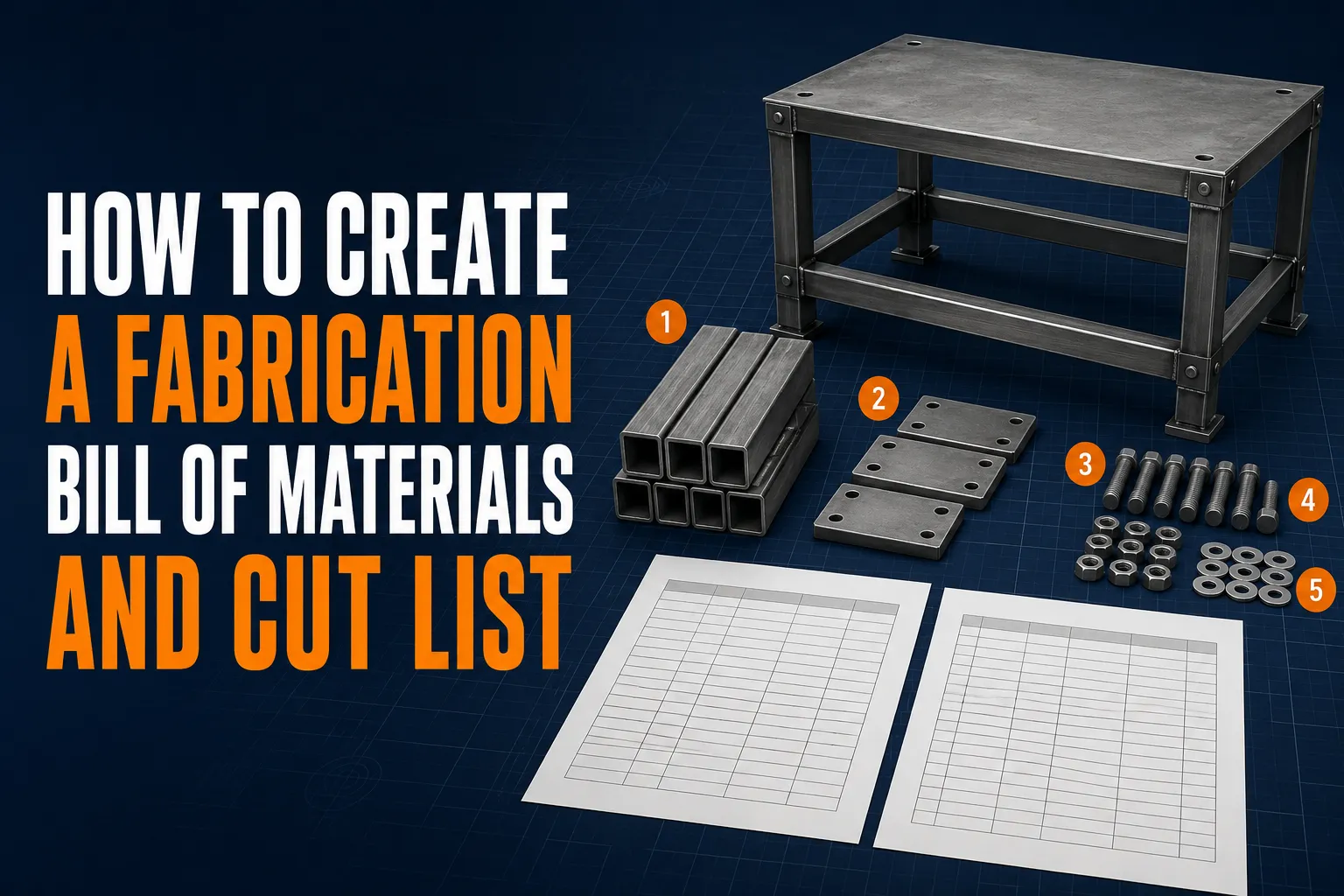
A fabrication design is not ready for production simply because the 3D model looks complete. Purchasing needs to know what material to order. Cutting needs lengths, profiles and quantities. Welding needs part identification. Assembly needs hardware and bought-in components. The bill of materials, or BOM, connects these activities.
The cut list is a focused production document for items made from stock lengths, sheets or plates. Together, a controlled BOM and cut list reduce missing parts, material substitutions, duplicated cutting and costly questions on the shop floor.
Understand the Difference
A BOM lists everything required to build the product. Depending on the project, it may include:
- fabricated parts;
- structural profiles;
- sheet and plate components;
- fasteners;
- hinges and handles;
- bearings or wheels;
- purchased assemblies;
- seals and insulation;
- finishing materials; and
- labels or packaging.
A cut list usually contains only items that must be cut from raw stock. Typical entries are square hollow section, angle, flat bar, pipe, round bar, sheet and plate. It may also record cut length, end angle, quantity and stock assignment.
Do not force both documents to perform every function. A BOM controls product content; a cut list supports a manufacturing operation.
Establish Part Numbers Early
Every unique component should have a unique part number. The identifier should appear consistently in the model, drawing, BOM, DXF filename and workshop labels.
A useful system is:
- simple enough for people to use;
- unique across the business;
- stable when descriptions change;
- compatible with software and filenames; and
- supported by revision control.
Avoid encoding too much information into the number. If a part number contains material, thickness, project, finish and date, a small design change may force renumbering. A sequential or lightly structured identifier is often easier to maintain.
Use a separate field for human-readable descriptions such as “left side panel” or “25 × 25 × 2 mm base rail.”
Define What Makes a Part Unique
Two components are not identical merely because their outer dimensions match. Differences that usually require separate identities include:
- hole position;
- handed geometry;
- bend direction;
- material grade;
- thickness;
- finish;
- machining;
- weld preparation; and
- quality or certification requirements.
Right-hand and left-hand parts need clear distinction. If one can be flipped to make the other without affecting grain, finish or features, document that intentionally rather than assuming it.
Use Clear BOM Columns
A practical fabrication BOM may include:
- item number;
- part number;
- revision;
- description;
- quantity per assembly;
- material specification;
- size or thickness;
- finish;
- manufacturing method;
- drawing or file reference;
- supplier part number; and
- remarks.
Not every project needs every column. Include information that controls purchasing and production, and avoid fields that are never maintained.
Material must be specific enough to prevent unsuitable substitution. “Steel” is rarely sufficient. State the grade or governing specification when design, welding, strength, corrosion resistance or certification depends on it.
Build a Workshop-Ready Cut List
For profiles cut from bar or tube, include:
- stock profile and wall thickness;
- finished cut length;
- quantity;
- end-cut angles;
- orientation of angled ends;
- machining or hole requirements;
- part number; and
- allowance instructions where relevant.
Clarify whether the listed length is the longest point, shortest point, centreline or theoretical intersection for mitres. A drawing or small end-view diagram prevents interpretation errors.
For plate and sheet, the DXF normally controls the outline, while the list identifies material, thickness, quantity and file revision. Do not ask the cutting operator to infer thickness from the filename alone.
Do Not Double-Count Quantities
Assemblies often have several levels. A table product may contain two leg assemblies, each with four braces. The top-level BOM should show two leg assemblies; the lower-level BOM should show four braces per leg assembly. An exploded or “flattened” BOM might show eight braces for the final product.
Define which view the document uses. Otherwise, purchasing may order four braces when production needs eight—or order both subassemblies and their individual parts twice.
For configurable products, state whether quantities are fixed, optional or selected by variant.
Link the BOM to the Drawings
Use numbered balloons on assembly drawings that match BOM item numbers. The item number helps readers locate a row; the part number identifies the component permanently.
Each fabricated part should point to the correct drawing, DXF or model revision. If a component is fully defined in an assembly drawing, make that relationship clear. Do not allow an old DXF and a revised drawing to share the same ambiguous filename.
Recommended filenames include the part number and revision, for example:
WBC-1042_REV-B_3MM.DXF
Keep material and thickness in controlled metadata as well, because filenames can be shortened, renamed or separated from the job pack.
Control Revisions
Revision control is essential when designs change after quotation or production has started. Record:
- the revision identifier;
- change description;
- date;
- author or approver;
- affected parts; and
- disposition of existing stock.
If a hole moves in one plate, update the part drawing, DXF, BOM reference and any related assembly documentation. Superseded files should be removed from production access or clearly marked obsolete.
Avoid labels such as “final,” “final2” and “latest.” They do not provide reliable history.
Include Scrap, Spares and Process Allowance Deliberately
Quantity per assembly should represent the product requirement, not an unrecorded estimate of production loss. If additional pieces are needed for setup, destructive testing or expected scrap, show them separately in the work order or purchasing calculation.
Similarly, stock-length optimisation belongs in cutting planning. The part length should remain the finished requirement. Saw kerf, end trim and stock defects can then be handled with explicit rules.
For critical hardware, a controlled spare quantity may be appropriate, but it should not be hidden inside the product BOM.
Verify Stock-Length Cutting
A correct list of part lengths can still waste material if it is not arranged into suitable stock lengths. Nest the cuts while considering:
- saw kerf;
- end trim;
- damaged stock ends;
- gripper or clamp allowance;
- reusable remnants;
- angled cuts; and
- available supplier lengths.
The best arrangement may not use the fewest bars if it increases handling or produces awkward remnants. Record the planned stock and label reusable offcuts.
Check Sheet and Plate Requirements
For nested flat parts, verify:
- sheet size;
- material and grade;
- thickness;
- grain or finish direction;
- part spacing;
- common-line cutting policy;
- edge margins;
- heat-sensitive features;
- quantity; and
- remnant identification.
The nesting software can optimize layout, but it cannot correct an inaccurate BOM. Compare the nest quantities against the released production quantities before cutting.
Add Make-or-Buy Information
A BOM should distinguish fabricated parts from purchased items. For bought-in parts, record the supplier or manufacturer part number, description and approved alternative where applicable.
For subcontracted operations such as laser cutting, bending, galvanizing or machining, identify the required input and output. The supplier may receive a DXF, drawing and quantity, while the workshop receives a finished part with certification or inspection records.
Avoid uncontrolled substitutions. A hinge with the same overall size may have a different load rating, hole pattern or corrosion resistance.
Perform Three Independent Checks
Before release, review the documentation from three perspectives.
Design check
Does every model component have the correct identity, material and quantity?
Purchasing check
Can someone order all raw material and hardware without opening the CAD model or guessing specifications?
Workshop check
Can an operator identify, cut and label each part without relying on memory?
Where possible, have another person compare the assembly drawing, BOM, cut list and files. Fresh eyes often find mirrored parts, missing hardware and quantity errors.
BOM and Cut-List Checklist
Before issue, confirm that:
- every unique part has a unique number;
- descriptions are clear;
- revisions match all drawings and files;
- quantities are correct at each assembly level;
- material grades and thicknesses are specified;
- profiles and cut lengths are unambiguous;
- mitre orientation is shown;
- sheet parts link to the correct DXF;
- purchased parts include supplier references;
- finishes and subcontract operations are listed;
- waste allowances are handled separately;
- stock nesting has been reviewed; and
- obsolete files cannot reach production.
Final Thoughts
An accurate BOM and cut list are not administrative extras. They are manufacturing controls. When part numbers, quantities, materials and revisions agree across every document, the shop can move from purchasing to cutting and assembly with fewer interruptions.
Build the documentation alongside the design, not after it. Verify it from the perspectives of purchasing and production, then release it as one controlled package. That discipline prevents small data errors from becoming expensive metal errors.

 No products in the cart.