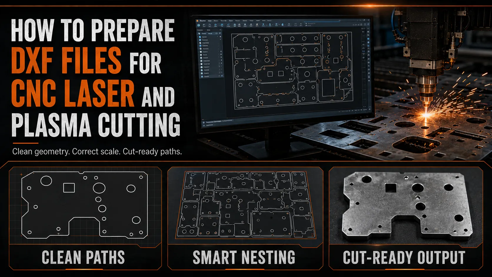
A DXF file may look correct on screen and still fail at the cutting machine. Open contours stop toolpath generation, duplicate lines cause double cutting, incorrect units change part size and stray geometry expands the nest. These errors waste programmer time and can damage material.
A production-ready DXF should communicate only the geometry the machine needs, supported by a PDF that explains material, thickness, quantity and critical requirements. This guide provides a practical preparation and checking workflow.
Understand What the DXF Controls
DXF is a common exchange format for two-dimensional CAD geometry. It can carry lines, arcs, circles, polylines, splines, text, blocks and layers. CNC software interprets selected entities as paths for cutting, marking or other operations.
The DXF usually defines profile geometry. It should not be expected to communicate every manufacturing requirement. Material grade, thickness, tolerances, bend direction, finish and revision belong in a companion drawing or job record.
Export at Full Scale
Create and export the part at 1:1 scale. Do not resize geometry to fit a drawing sheet. Confirm whether the source model and exported file use millimetres or inches.
After export, open the DXF in a separate program and measure a known dimension. This independent check catches unit conversion and scale errors before the file reaches production.
Include a PDF with at least one overall reference dimension. The cutter can compare the imported geometry against it.
Use Clean, Closed Contours
Every profile intended for cutting should form a closed loop unless the operation is explicitly an open-line mark or slit.
Common contour problems include:
- tiny gaps between endpoints;
- overlapping segments;
- lines that extend beyond corners;
- self-intersecting polylines;
- circles made from disconnected arcs;
- duplicate geometry; and
- stacked outlines on different layers.
Use CAD cleanup tools to join endpoints, find duplicates and detect open profiles. Zoom into corners rather than relying only on the full-screen view.
Remove Duplicate Lines
Duplicate lines may cause the machine to cut the same path twice. That adds heat, enlarges the kerf, damages the edge and wastes consumables.
Duplicates often appear when:
- several faces are projected onto one sketch;
- blocks are exploded repeatedly;
- files are copied between CAD systems;
- separate layers contain identical outlines; or
- a flat pattern and manual tracing are both exported.
Run an overkill or duplicate-removal function, then inspect the result. Automated cleanup should not delete intentional close features.
Simplify Entity Types
Most CAM systems handle lines, arcs, circles and polylines reliably. Splines and ellipses may be supported, but conversion can create thousands of short segments or change the shape.
Where required by the cutting supplier, convert complex curves into controlled arcs or polylines with an appropriate tolerance. Do not use such a coarse approximation that circles become visibly faceted, or such a fine one that the controller receives excessive data.
Ask the supplier which DXF version and entity types their software prefers.
Separate Operations With Layers
Use clear layers for different manufacturing instructions, for example:
- CUT_OUTER;
- CUT_INNER;
- MARK;
- ETCH;
- BEND_UP;
- BEND_DOWN; and
- REFERENCE.
Layer names are only helpful if the supplier agrees with their meaning. Provide a legend in the PDF. Do not assume a machine will automatically understand a red line as a bend or a dashed line as marking.
Remove dimensions, borders, title blocks and construction geometry from the production cutting layer. Otherwise the CAM operator may import them as toolpaths.
Keep Bend Lines Out of Cut Geometry
For sheet-metal parts, bend lines may be useful for marking or setup, but they must be clearly separated from through-cut contours. Export them on dedicated layers or in a separate reference file according to the supplier’s workflow.
State bend direction, angle and radius on a PDF bending drawing. A flat DXF alone does not fully define the formed part.
Handle Text and Logos Correctly
Ordinary CAD text may substitute fonts or disappear on another computer. If text must be cut, convert it to outlines and confirm that letters have bridges where required. If text must only be marked, use the supplier’s supported marking entities.
Check logos for:
- excessive detail;
- intersecting paths;
- tiny islands;
- duplicate outlines; and
- copyright or licensing restrictions.
Keep product identification readable after coating and at the actual cut size.
Design Features for the Cutting Process
Very small holes, narrow slots and thin webs may not cut reliably. Capability depends on process, material, thickness, machine and quality requirement.
Do not apply one universal “minimum hole equals thickness” rule. Ask the actual cutter. If a critical hole is below reliable thermal-cut capability, use a pilot hole followed by drilling or machining.
Sharp internal corners may receive a small process radius. If the mating part truly requires a sharp corner, consider dog-bone relief, machining or design clearance.
Do Not Apply Kerf Compensation Blindly
Kerf is the width removed by the cutting process. CAM software normally offsets the toolpath to maintain the designed profile. If the designer also offsets the DXF without agreement, compensation may be applied twice.
Supply nominal finished geometry unless the cutter specifically requests pre-compensated files. Document any intentional compensation clearly.
The same principle applies to hole shrinkage, bevel compensation and waterjet taper: agree on responsibility between design and CAM.
Control Part Orientation
Orientation may matter because of:
- rolling grain;
- brushed or patterned finish;
- mechanical properties;
- bend-cracking risk;
- plasma cut direction;
- visible surface; and
- heat distribution.
Add a grain or finish arrow to the PDF and, if requested, a non-cut reference layer. Do not add an arrow to the cutting layer where it could become scrap geometry.
Include Part Identification
File names should be stable and unique. A useful pattern is:
Project-PartNumber-Description-Revision-Quantity.dxf
Avoid names such as “final2-new-revised.dxf.” Maintain revision control and archive superseded files away from the active production folder.
For multiple parts, provide a cut list or nest manifest showing file name, material, thickness and quantity.
Export Flat Patterns From the Model
For bent parts, use the CAD system’s sheet-metal flat-pattern function rather than manually redrawing the profile. The flat pattern should reflect the approved bend table, K-factor or deduction data.
Before release, refold the model digitally and verify the finished dimensions. Autodesk Fusion can create drawings, nests, reports and cutting strategies for sheet-based fabrication, as described in its fabrication workflow overview.
Perform an Independent Import Test
Do not validate the DXF only in the program that created it. Import it into a second CAD or CAM viewer and check:
- overall dimensions;
- entity count;
- closed contours;
- layers;
- arcs and circles;
- text conversion;
- duplicated paths; and
- the bounding box.
If possible, run a CAM preview. Confirm that internal holes cut before external profiles and that every required profile is recognized.
Provide a Companion PDF
The PDF should state:
- project and part name;
- revision;
- units;
- material grade and thickness;
- quantity;
- overall reference dimension;
- critical tolerances;
- finish direction;
- marking requirements;
- bend information; and
- contact details for clarification.
The PDF is the human-readable reference; the DXF is the machine geometry. Both should agree.
Common DXF Mistakes
Frequent errors include exporting drawing-sheet borders, leaving dimensions in the cut layer, sending a model-space file at the wrong units, applying kerf compensation twice, failing to convert a logo, leaving splines unsupported and mixing revisions in one ZIP package.
Another mistake is nesting parts manually in the product file without permission. Many cutters prefer individual part DXFs so their CAM system can apply process-specific spacing, lead-ins and quantities.
Final DXF Checklist
- Geometry is 1:1 and units are confirmed.
- A known dimension has been measured after export.
- Cut contours are closed.
- Duplicate and stray entities are removed.
- Supported lines, arcs and polylines are used.
- Cut, mark and bend operations are separated.
- Dimensions and borders are excluded from cut layers.
- Kerf has not been pre-compensated without agreement.
- Material, thickness, quantity and revision are documented.
- A companion PDF is included.
- The file has passed an independent import check.
Conclusion
A clean DXF reduces programming time and protects material. Export at full scale, use closed contours, remove duplicates, separate operations, control feature size and verify the file in independent software.
Most importantly, pair machine geometry with a clear fabrication drawing. That combination gives the cutter both the exact profile and the manufacturing intent needed to produce the right part.
 No products in the cart.