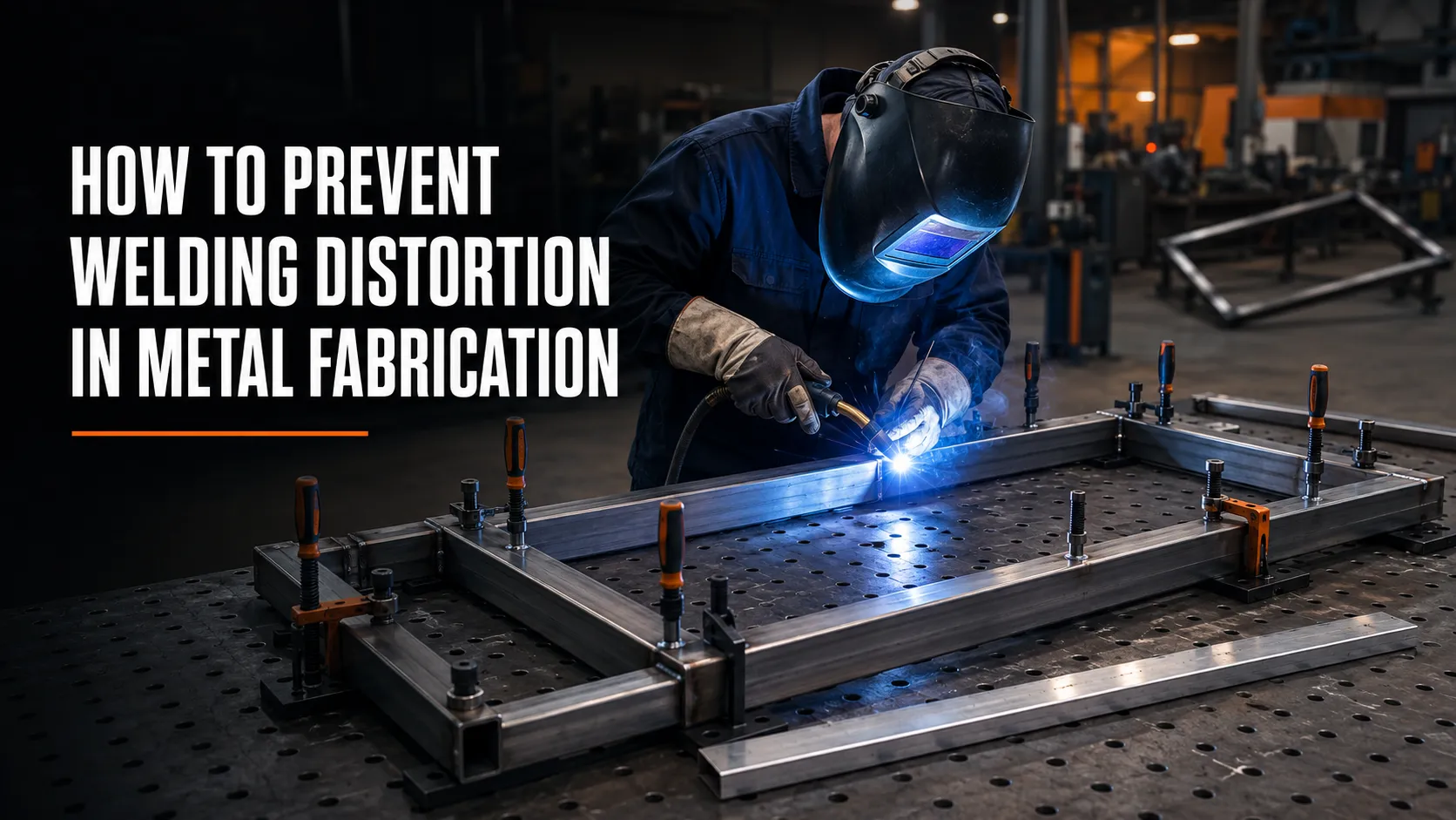
Welding distortion can turn accurate parts into a twisted assembly. A frame that was square before welding may pull into a diamond. A flat sheet may develop waves. A bracket may close or open its angle. Correcting these problems costs time and can introduce new stresses or surface damage.
Distortion is not random. It results from uneven heating, expansion and contraction. Once a workshop understands where shrinkage will occur, it can control much of the movement through design, fit-up, restraint and welding sequence.
Why Welded Metal Moves
The weld zone becomes hot and expands. Surrounding cooler metal restrains that expansion. When the weld solidifies and cools, it contracts. Because the heating and cooling are not uniform across the component, contraction pulls the assembly out of shape.
The amount of movement depends on:
- heat input;
- weld size and length;
- joint position relative to the neutral axis;
- material thickness and thermal properties;
- assembly stiffness;
- degree of restraint;
- fit-up and root gap; and
- welding sequence.
Common Types of Distortion
Angular distortion
Unequal contraction through the material thickness changes the angle between parts. This is common in single-sided fillet welds and single-V butt joints.
Longitudinal shrinkage
Contraction along the weld length can shorten or bow a component. Long welds near one edge are especially influential.
Transverse shrinkage
Contraction across the joint can close a root gap or reduce the overall width of an assembly.
Buckling and bowing
Thin sheet and slender members can lose stability under compressive shrinkage stress, producing waves, bows or oil-canning.
Twisting
Asymmetrical weld placement or sequence can rotate long frames and channels.
Identifying the likely distortion mode helps the fabricator choose an effective control method.
Control Distortion at the Design Stage
The most efficient distortion control begins before fabrication.
Use only the required weld size
Oversized welds deposit more metal and introduce more heat. Weld size should be determined by the design and shown on the drawing. “Bigger for safety” can produce more distortion without improving the actual connection.
Balance welds around the neutral axis
Where design permits, place welds symmetrically. Double-sided joints can balance shrinkage better than an equivalent single-sided joint. Intermittent welds may be acceptable for non-sealed connections when the design permits them.
Reduce unnecessary weld length
Continuous welding should not be specified automatically where intermittent welds satisfy structural, sealing and corrosion requirements. Never change a specified continuous weld without design approval.
Select stable sections
Closed sections and formed profiles often resist distortion better than wide, unsupported sheet. Add bends, ribs or returns where they serve the product design and can be manufactured economically.
Improve Cutting and Fit-Up
Accurate parts need less force and filler metal during assembly. Excessive root gaps increase weld volume and heat. Misaligned edges require larger beads or grinding. Components forced into a fixture store elastic stress that may release after unclamping.
Check:
- cut-edge squareness;
- bevel angle and root face;
- root opening;
- part length;
- straightness; and
- contact between mating surfaces.
Miller advises assessing joints for excessive gaps and clamping parts in the correct position because poor fit-up can contribute to burn-through and distortion; see its review of common welding operation mistakes.
Use Tacks Properly
Tack welds hold alignment and distribute shrinkage before final welding. They should be clean, sound and large enough for the assembly but not so large that they become difficult to blend into the finished weld.
Use enough tacks to prevent the joint from progressively closing. TWI notes that tack number, length and spacing affect control of root-gap closure. Place tacks in a balanced sequence rather than starting at one end and moving continuously to the other.
Inspect every tack. Remove cracked, porous or poorly fused tacks instead of covering them. Recheck dimensions after tacking because the assembly may already have moved.
Plan the Welding Sequence
The sequence controls how shrinkage accumulates.
Weld from the centre outward
On symmetrical assemblies, working from the centre toward free ends can distribute movement rather than driving it into one location.
Alternate sides
For frames, brackets and double-sided joints, alternate between opposing areas so heat and shrinkage remain balanced.
Use back-step welding
The overall welding direction moves forward, but each short segment is deposited in the opposite direction. This can distribute contraction on suitable joints.
Skip around the assembly
On sheet or long seams, weld separated sections and allow heat to spread before connecting them. Do not place every weld consecutively in one hot area.
Complete symmetrical welds in stages
Divide long welds into manageable lengths. Deposit comparable amounts on opposite sides before one side accumulates most of the shrinkage.
The correct sequence must still comply with the WPS and avoid start-stop defects in critical regions.
Control Heat Input
Excessive heat enlarges the hot zone and increases shrinkage. Use the approved combination of current, voltage, travel speed and process. Avoid weaving wider than required, repeatedly reheating the same area or depositing oversized beads.
High-productivity processes can sometimes reduce distortion because faster travel produces less total heat per unit length. However, inadequate heat creates lack of fusion. The objective is controlled, sufficient heat—not simply the lowest possible setting.
Monitor interpass temperature where specified. Thin stainless steel and aluminium are especially sensitive to accumulated heat, though they behave differently and require material-specific procedures.
Use Fixtures and Restraint Wisely
Jigs, strongbacks, clamps and temporary stiffeners can hold an assembly during welding. Fixtures also improve repeatability in production.
Good restraint practice includes:
- locating from stable datums;
- clamping close enough to the joint to control movement;
- leaving access for the torch and inspection;
- avoiding damage to finished surfaces;
- allowing thermal expansion where necessary; and
- checking that clamps do not hide a missed weld.
Excessive restraint does not eliminate shrinkage; it can increase residual stress and cracking risk. The fixture must support the welding plan rather than fight every movement blindly.
TWI describes tack welding, stiffening and back-to-back assembly among practical distortion-control fabrication techniques.
Use Presetting Carefully
Presetting intentionally positions parts opposite the expected movement so contraction pulls them toward the correct final shape. This can work well on repeat products after the workshop establishes reliable behavior through trials.
Do not guess a large preset on a one-off critical assembly. Record the measured movement from procedure trials and adjust fixtures gradually.
Manage Thin Sheet Differently
Thin panels require special care because they buckle easily. Use tight fit-up, small controlled tacks, short weld segments and adequate cooling intervals where the procedure permits. Support the panel with a flat fixture or heat sink when appropriate.
Avoid unnecessary continuous seams. If a joint needs sealing, consider the specified process and sequence rather than trying to close the seam with a long, slow bead. Miller’s guidance for auto-body sheet recommends short, controlled welding and cooling to limit distortion, but every production procedure must match its material and service.
Measure During Fabrication
Do not wait until the assembly is complete. Check:
- diagonals;
- straightness;
- flatness;
- angles;
- opening dimensions; and
- alignment of mounting holes.
Measure after tacking, after major weld stages and before removing strongbacks. Mark hold points on the traveler or drawing. Early correction is usually easier than straightening a finished, coated assembly.
Correcting Distortion
Correction methods include mechanical straightening, controlled heat straightening and cutting or rewelding under an approved repair plan. Each method can change residual stress, dimensions or material properties.
Never heat-straighten high-strength, heat-treated or unknown materials without a qualified procedure. Avoid hammering critical welds or grinding them below the specified size. If the component is safety-critical, obtain engineering approval for the correction.
Distortion-Control Checklist
Before welding, confirm:
- correct joint design and weld size;
- accurate cutting and fit-up;
- balanced tack pattern;
- fixture and datum plan;
- welding sequence marked;
- correct process and parameters;
- interpass limits understood;
- inspection points established; and
- preset based on evidence rather than guesswork.
Conclusion
Welding distortion is caused by predictable thermal expansion and contraction. It can be controlled by reducing unnecessary weld metal, balancing joints, improving fit-up, using proper tacks, planning the welding sequence, controlling heat and measuring throughout production.
The most effective workshop does not wait for a warped assembly and then reach for a large hammer. It designs and plans the job so that the finished component arrives at the correct shape with minimal correction.
 No products in the cart.