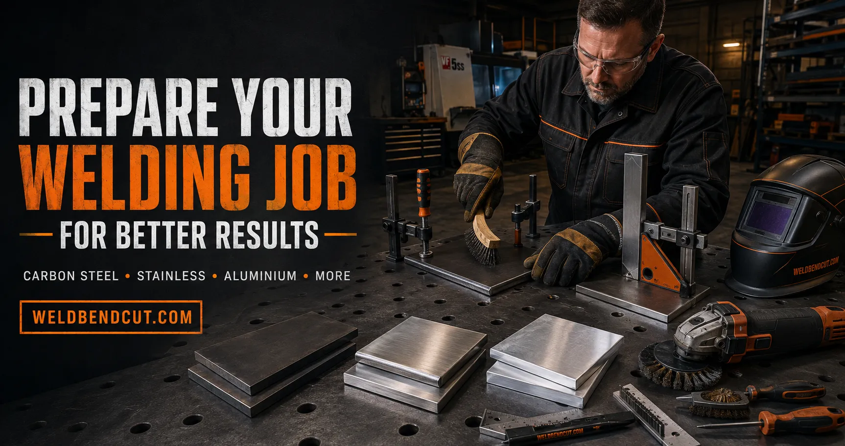
A good weld begins before the arc is struck. Incorrect material identification, dirty joint faces, poor fit-up, damp consumables or the wrong filler metal can cause porosity, cracking, lack of fusion, distortion and premature failure.
This guide gives fabricators a clear preparation process for carbon steel, stainless steel, aluminium, galvanized metal, cast iron and other common alloys.
Important: For structural, pressure, lifting, vehicle, pipeline or other safety-critical work, always use an approved welding procedure specification (WPS), qualified personnel and the required inspection plan. This guide supports good workshop practice but does not replace project specifications or applicable codes.
1. Understand the Job Before Cutting
Start with the drawing, model or fabrication plan. Confirm:
- the finished dimensions and tolerances;
- material grade and thickness;
- joint type and weld size;
- welding process and position;
- filler metal and shielding gas;
- preheat, interpass and post-weld requirements;
- inspection and acceptance requirements; and
- the required surface finish or protective coating.
Resolve missing or conflicting information before production begins. A neat weld in the wrong location, on the wrong grade or at the wrong size is still a failed job.
2. Identify the Base Metal Correctly
Never select settings or filler metal by appearance alone. Similar-looking metals can have very different welding requirements.
Check the material certificate, purchase record, grade marking or traceability tag. Use positive material identification when the grade is uncertain and the job is critical. Also confirm whether the part is cast, forged, heat-treated, plated, painted or previously exposed to oil or chemicals.
If two different metals must be joined, treat the connection as a dissimilar-metal weld. Filler selection and heat input may require engineering or metallurgical guidance.
3. Make the Work Area Safe
Remove combustible materials from the welding area or protect them from heat, sparks and slag. Provide the required fire extinguisher and fire watch. Check that welding leads, the electrode holder or torch, gas hoses, regulator and work clamp are in good condition.
Provide effective ventilation and local fume extraction. Paint, galvanizing, plating, oil and solvent residues can produce hazardous fumes when heated. OSHA advises cleaning coatings that could create toxic exposure and requires suitable ventilation for welding operations. See the OSHA welding standards and its guidance on controlling welding fumes and gases.
Wear the correct helmet shade, safety glasses, flame-resistant clothing, gloves, hearing protection and safety footwear. Use respiratory protection only as part of an appropriate exposure-control programme.
Never weld, cut or heat a tank, drum, pipe or closed container until a qualified safe-work procedure confirms that it has been isolated, cleaned, tested and properly vented. Do not use chlorinated cleaners for weld preparation.
4. Inspect, Cut and Form the Parts Accurately
Inspect material for cracks, laminations, deep corrosion, dents, heavy pitting and incorrect thickness. Repair or reject defective material according to the job requirements.
Cut parts accurately and remove burrs, slag and sharp edges. Straighten distorted pieces before assembly. When bending is required, verify the bend direction, inside radius, allowance and grain orientation where relevant.
Accurate parts reduce forced fit-up, excessive gaps and unnecessary weld metal.
5. Prepare the Joint
The joint must provide access for the arc and enough space to achieve the required penetration without excessive weld volume.
Confirm:
- root face;
- root opening;
- bevel angle;
- joint alignment;
- backing or back-gouging requirements; and
- weld access from each side.
Thin sheet may require square edges, while thicker plate commonly requires a bevel or groove. Do not choose a bevel by habit—follow the drawing or WPS.
After beveling, remove cutting oxide, slag and gouging residue. Check the prepared edges with a gauge or template before assembly.
6. Clean the Weld Zone in the Correct Order
Cleanliness is essential even when using a process that tolerates some surface contamination. A reliable sequence is:
- Remove oil, grease, marker residue and moisture with an approved cleaner.
- Allow the cleaner to evaporate completely.
- Remove rust, oxide, mill scale, paint or plating as required.
- Clean both faces of the joint and the area where the work clamp will connect.
- Prevent recontamination from dirty gloves, benches, compressed air or shared tools.
Do not grind oil into the surface. Degrease first when the metal and cleaning procedure require it.
7. Adjust Preparation for the Metal
Carbon and mild steel
Remove oil, paint, moisture, loose rust, slag and heavy mill scale from the weld zone. Clean the work-clamp location to sound metal. Use suitable carbon-steel brushes or grinding tools. For thicker butt joints, prepare the specified bevel and root gap.
Low-alloy and higher-carbon steels may require low-hydrogen consumables, controlled preheat and restricted heat input. Do not apply mild-steel settings automatically to an unknown alloy.
Stainless steel
Use brushes, files, abrasives and grinding discs dedicated exclusively to stainless steel. Tools previously used on carbon steel can transfer iron contamination and reduce corrosion resistance. Miller recommends dedicated preparation tools and close fit-up for stainless work; see its stainless steel tube and pipe guidance.
Remove oil, adhesive, paint and heat tint as required by the specification. Control fit-up and heat input to limit distortion. Stainless pipe, sanitary work and corrosion-critical joints may require an inert-gas root purge.
Aluminium
Aluminium must be dry and free of oil, grease and oxide. Clean it in the correct order: degrease first, then remove the oxide using a clean stainless-steel brush reserved only for aluminium or another approved method. Brushing before degreasing can embed hydrocarbons in the surface. Miller provides a detailed aluminium cleaning sequence.
Clean both sides of the joint, protect the filler wire from dust and moisture, and weld soon after final cleaning. Use sharp cutting tools that do not smear contaminants into the edge.
Galvanized, painted or plated metal
Identify the coating before disturbing it. Zinc, lead, cadmium and other coatings require specific exposure controls. Do not assume that every plated component is ordinary galvanized steel.
Remove the coating from the weld zone only as required by the approved procedure, use effective local exhaust ventilation and wear the specified PPE. Keep other workers away from the fume path. After welding and inspection, restore corrosion protection using the specified repair system.
Cast iron
Identify the casting grade before selecting a repair method. White iron is generally considered unweldable, while grey, ductile and malleable irons require different procedures.
Remove paint, oil, casting skin and contamination from the repair area. Oil may be absorbed into an old casting and require repeated cleaning. Select the correct filler, preheat method and cooling plan before welding. Cast iron is sensitive to rapid temperature changes, so uncontrolled local heating can cause cracking. TWI recommends alloy identification, thorough cleaning, controlled preheating and slow cooling in its cast-iron welding guide.
Copper, brass and bronze
Remove oxides, oil and dirt, and confirm the exact alloy. Copper alloys conduct heat rapidly, so thicker parts may require controlled preheat. Brass contains zinc and needs particularly effective fume control. Match the filler and heat-input plan to the alloy and service requirement.
Nickel alloys and titanium
These metals demand strict cleanliness, dedicated tools and reliable shielding. Keep joint faces, filler metal, gloves and work surfaces clean. Titanium often requires trailing shielding or back purging to protect hot metal from air. Follow an alloy-specific WPS; colour or surface appearance alone is not enough to approve the weld.
8. Fit, Clamp and Tack the Assembly
Dry-fit the complete assembly before final welding. Check overall dimensions, diagonals, squareness, level, alignment and moving-part clearances.
Use clamps and fixtures that hold the parts without forcing them into position. Excessive force stores stress in the assembly and can increase distortion or cracking.
Tack welds should be clean, correctly sized and placed according to the planned sequence. Defective tacks must be removed rather than buried under the final weld. Recheck dimensions after tacking because the assembly can move as the tacks cool.
9. Prepare the Machine and Consumables
Before welding:
- confirm the correct process, polarity and programme;
- select the specified filler classification and diameter;
- keep electrodes and flux-cored consumables dry as required by the manufacturer;
- verify the shielding-gas type, flow and hose condition;
- inspect the contact tip, liner, nozzle, collet and tungsten;
- connect the work clamp to clean metal close to the weld; and
- verify that cables and connections are tight and undamaged.
For gas-shielded welding, protect the joint from strong drafts. Excessive gas flow can also create turbulence and draw air into the shielding envelope.
10. Control Preheat and Interpass Temperature
Do not preheat every metal automatically. Preheat depends on alloy, thickness, restraint, hydrogen level, ambient conditions and the applicable code or WPS.
Where preheat is specified, heat the required area evenly and measure the temperature with an appropriate device. Maintain the permitted interpass range between weld runs. TWI explains that preheat is measured before welding, while interpass temperature controls the condition before subsequent passes; both must follow the qualified procedure. See its guidance on preheat and interpass temperature.
11. Make a Test Weld and Plan the Sequence
For unfamiliar material, a new machine setup or a critical appearance requirement, make a test weld on matching scrap. Confirm penetration, bead profile, fusion, distortion and surface condition before welding the actual component.
Plan the welding sequence to balance shrinkage. Use short, controlled runs where appropriate, alternate sides or positions, and allow cooling only as permitted by the WPS. Do not compensate for poor fit-up by depositing unnecessarily large welds.
12. Inspect Before, During and After Welding
Inspect preparation before the joint becomes inaccessible. During welding, remove slag and contamination between passes and check for cracks, undercut, lack of fusion, porosity and arc strikes.
After welding:
- allow the component to cool according to the procedure;
- perform the required visual and nondestructive examination;
- verify final dimensions and moving clearances;
- remove spatter and temporary attachments correctly;
- repair defects using an approved method; and
- restore paint, galvanizing, passivation or other corrosion protection.
Never grind away a weld simply to make it look smooth unless the drawing and required weld size allow it.
Final Pre-Welding Checklist
Before striking the arc, confirm:
- Correct drawing revision and dimensions
- Correct material grade and thickness
- Correct joint preparation and root gap
- Joint and clamp areas clean and dry
- Correct filler, gas and polarity
- Consumables stored and prepared correctly
- Assembly square, aligned, clamped and rechecked after tacking
- Required preheat achieved and measured
- Welding sequence understood
- Ventilation, PPE and fire controls in place
- Inspection requirements understood
Conclusion
Better welding results come from controlling the entire job, not only the arc. Identify the metal, follow the drawing and WPS, prepare the joint accurately, clean it using the correct metal-specific method, control fit-up and temperature, and inspect every stage.
Ten minutes spent preparing correctly can prevent hours of grinding, repair and refabrication—and can make the difference between a weld that merely looks good and one that performs safely in service.
Leave your comment and recommendation according to your experience.
 No products in the cart.