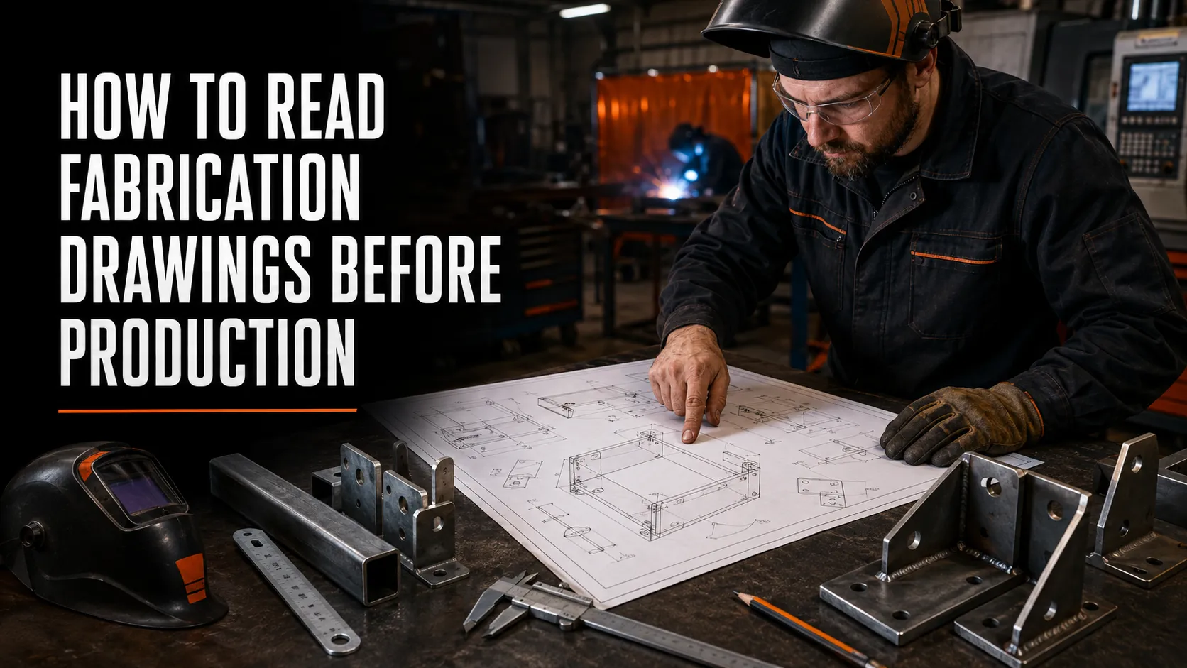
Fabrication drawings are the link between a design idea and the finished metal product. They tell the workshop what to cut, bend, drill, weld, assemble and inspect. When a drawing is read correctly, production becomes predictable. When it is misunderstood, even skilled workmanship can produce the wrong part.
The best time to find a drawing problem is before material is cut. A short review can prevent wasted sheet, incorrect hole positions, reversed bends, undersized welds and assemblies that do not fit. This guide explains a practical method for reviewing fabrication drawings before production begins.
Begin With the Title Block
The title block identifies the document and its controlling information. It is commonly placed in the lower-right corner and may include:
- drawing or part name;
- drawing number;
- revision number;
- scale;
- units;
- material specification;
- general tolerances;
- drawing date; and
- approval or checking information.
Never assume that the units are millimetres because the workshop normally uses metric measurements. Confirm the units on every drawing. Also confirm the revision. An accurate part made from an obsolete revision is still incorrect.
If a package contains general arrangements, individual part drawings, DXF files and bending sheets, verify that all files carry the same revision. A changed hole pattern in the PDF must also appear in the cutting file.
Understand the Drawing Hierarchy
A complete fabrication package may contain several document types:
- General arrangement drawing: shows the finished product, overall dimensions and relationship between assemblies.
- Assembly drawing: shows how parts connect, including welds, fasteners and item numbers.
- Part drawing: defines one component with its size, holes, material and manufacturing details.
- Flat pattern or cutting file: provides the developed shape used for CNC cutting.
- Bending drawing: identifies bend lines, directions, angles and radii.
- Bill of materials: lists materials, quantities, sections and purchased components.
Read the general arrangement first. It gives context for the smaller drawings. Then trace every item number from the assembly to its part drawing and bill of materials entry.
Read Orthographic and Isometric Views
Most fabrication drawings use front, top and side views to describe shape accurately. An isometric view helps with visual understanding but should not normally be used for measurement unless dimensions are specifically provided.
Follow projection lines between views. A hole that appears circular in one view may appear as hidden lines in another. Hidden lines show features behind a visible surface, while centre lines identify axes, hole centres and symmetry.
Section views reveal internal details by representing the component as if it has been cut. Detail views enlarge small or complicated areas. Always check whether a feature is shown elsewhere before concluding that information is missing.
Follow Dimensions, Not the Picture
Fabrication must follow stated dimensions rather than visual proportions. Drawings may be reduced, enlarged or printed incorrectly. The note “do not scale” means that dimensions must not be taken with a ruler from the page.
Build a dimension chain in your mind:
- overall length, width and height;
- datum or reference edges;
- hole and slot positions;
- edge distances;
- bend locations;
- material thickness; and
- clearances between moving or mating parts.
Avoid calculating a missing dimension unless the drawing clearly intends it. If two dimensions conflict, stop and request clarification. Do not choose the value that appears easier to fabricate.
Understand Tolerances
A tolerance defines the permitted variation from a nominal dimension. Some dimensions have individual tolerances, while others are controlled by a general tolerance in the title block.
Tighter tolerances usually require more careful cutting, machining, inspection and cost. Apply them where they matter: mating parts, bearing locations, aligned holes, sliding components and interfaces with purchased equipment. Do not assume every dimension needs machining-level accuracy.
Geometric controls may define flatness, perpendicularity, parallelism, position or runout. If a symbol is unfamiliar, consult the applicable drawing standard or the designer. Guessing at a geometric requirement can make a part unusable.
Read Welding Information Carefully
Weld symbols communicate joint location, weld type, size, length, pitch, side and finishing requirements. The arrow points to the joint, while the symbol’s position relative to the reference line identifies the arrow side or other side.
Check whether the weld is:
- a fillet, groove, plug, slot or spot weld;
- continuous or intermittent;
- required on one side or both sides;
- applied all around the joint;
- completed in the workshop or in the field;
- ground flush, blended or left as welded; and
- subject to a specified welding procedure or inspection method.
Do not increase a weld simply because a larger bead looks stronger. Oversized welds add heat, filler metal, time and distortion. TWI notes that weld size should be determined by calculation and specification rather than informal rules of thumb in its guidance on fillet-welded joints.
For safety-critical work, the approved welding procedure specification controls filler, process, preheat and other essential variables.
Check the Bill of Materials
The bill of materials, or BOM, connects item numbers to physical materials. Confirm:
- material grade;
- section size and wall thickness;
- sheet or plate thickness;
- cut length;
- quantity;
- purchased hardware; and
- finish or coating.
“Steel” is not a complete material specification for critical work. Likewise, two square tubes with the same outside dimensions may have different wall thicknesses and capacities.
Compare the BOM with the part drawings. If the drawing shows eight brackets and the BOM lists six, resolve the difference before nesting or purchasing material.
Review Cutting and Bending Information
For CNC-cut parts, open the DXF file and verify that its outline matches the drawing. Check for duplicate lines, open contours, stray geometry, incorrect scale, missing holes and text that has accidentally been converted into cutting paths.
For bent components, confirm:
- which face is considered inside or outside;
- bend direction—up or down;
- angle;
- inside radius;
- bend sequence;
- relief details; and
- final dimensions after bending.
A flat pattern is not simply the sum of finished flange lengths. Bend allowance, bend deduction, material thickness and tooling affect the developed size. Autodesk explains how thickness, angle, inside radius and K-factor are used when determining sheet-metal flat lengths in its sheet-metal fabrication guide.
Perform an Assembly Review
Before production, imagine the complete assembly sequence. Ask:
- Can every weld be reached with the selected process?
- Can bolts be inserted and tightened?
- Are there clashes between brackets, doors and frames?
- Is there room for a press-brake tool around each bend?
- Can the part be clamped and inspected?
- Will a closed section trap gas during welding or coating?
- Can the finished assembly be transported through available doors and vehicles?
The design should also permit any required inspection. TWI emphasizes that joint design must allow the specified nondestructive testing to be performed, not merely allow the weld to be deposited.
Create a Production Plan
Convert the drawing package into a practical sequence:
- Purchase and identify material.
- Cut primary parts.
- Drill, machine or form features.
- Bend sheet-metal components.
- Deburr and prepare edges.
- Assemble in jigs or fixtures.
- Tack and verify dimensions.
- Weld in a distortion-controlled sequence.
- Inspect and correct defects.
- Finish, coat and perform final assembly.
Mark critical hold points, such as checking dimensions before closing a box section or confirming door operation before coating.
Common Drawing-Reading Mistakes
Frequent workshop errors include using the wrong revision, confusing radius and diameter, missing “typical” or “equal spacing” notes, reversing a bend, scaling from a printed view, overlooking a section view and treating reference dimensions as manufacturing controls.
Another mistake is reviewing each part independently without checking the assembly. A bracket can match its own drawing but still interfere with a neighboring component because of a revision mismatch.
Pre-Production Drawing Checklist
Before cutting, confirm:
- correct drawing and revision;
- correct units and scale information;
- material grade, thickness and quantity;
- all dimensions and tolerances are understood;
- every item number has a matching part;
- weld symbols and procedures are clear;
- DXF geometry matches the part drawing;
- bend directions and angles are confirmed;
- purchased parts and clearances are verified; and
- missing or conflicting information has been resolved.
Conclusion
Reading fabrication drawings is not an office-only task. It is a production skill that protects material, labor and quality. Begin with the title block, understand the drawing hierarchy, follow dimensions and tolerances, verify weld and bend information, compare the BOM and plan the assembly sequence.
The few minutes spent reviewing a drawing package can save hours of cutting, grinding and refabrication. In a small or medium workshop, that discipline is one of the simplest ways to improve accuracy and profitability.


 No products in the cart.