Sheet-metal bending looks simple: place a flat part in a press brake and form it to an angle. In reality, the finished dimensions depend on material thickness, inside radius, tooling, grain direction, bend method and elastic springback. A flat pattern that ignores these factors may produce flanges that are too long, holes that move out of position or parts that cannot be assembled.
This guide explains the essential bending concepts designers and fabricators need before creating cutting files or press-brake instructions.
What Happens During a Bend
When sheet metal bends, the outside surface stretches while the inside surface compresses. Between them lies a neutral axis whose length changes much less than the surrounding material.
The neutral axis does not normally remain at the exact centre of the thickness. Its position depends on material, radius, tooling and forming method. That is why the developed flat length cannot be calculated by simply adding finished flange dimensions.
Autodesk defines the K-factor as the ratio locating the neutral axis within the material thickness and explains how thickness, angle, inside radius and K-factor affect bend allowance in its sheet-metal fabrication overview.
Key Bending Terms
Material thickness
The actual sheet thickness affects bend geometry and tool selection. Nominal thickness may differ slightly from measured stock, so production work should use verified material data and an approved gauge table where appropriate.
Inside bend radius
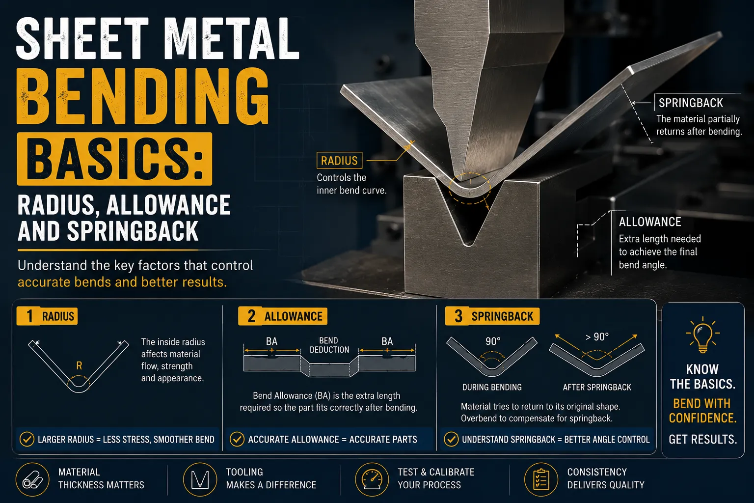
The radius measured on the inside of the formed bend. It is influenced by punch radius, die opening, material strength, thickness and bending method.
Bend angle
The amount of forming required. Drawings must clearly state whether the dimension describes the included angle or the angle through which the metal is bent.
K-factor
The ratio between the neutral-axis location and material thickness. It is used to estimate the arc length of the neutral axis during bending.
Bend allowance
The length of the neutral-axis arc within the bend zone. A common theoretical form is:
Bend allowance = bend angle in radians × (inside radius + K-factor × thickness)
This is a model, not a universal production answer. Actual tooling and material behavior should be verified through shop data or test bends.
Bend deduction
The amount subtracted from the sum of outside flange dimensions to obtain the flat length. Some workshops prefer bend deduction because it aligns directly with outside dimensions on drawings.
Outside setback
The distance from the bend tangent point to the theoretical sharp outside corner. It connects bend geometry to flange measurements.
Air Bending, Bottoming and Coining
The forming method affects radius, force, accuracy and springback.
Air bending
The punch presses the sheet partway into the V-die without forcing it completely against the die faces. The bend angle depends on ram depth, and the inside radius is influenced strongly by the die opening and material. Air bending is flexible because one tool set can produce several angles.
Bottoming
The sheet is brought into closer contact with the punch and die geometry near the bottom of the stroke. It generally requires more force and less angular adjustment than air bending.
Coining
Very high pressure plastically compresses the bend region into the tool shape. It can reduce springback but requires significantly more force and is not the normal choice for many general-fabrication parts.
The bending file should match the method actually available in the workshop. A flat pattern calibrated for one process may not be accurate on another.
Understanding Springback
After the force is removed, elastic recovery causes the material to open slightly toward its original shape. This is springback.
Springback varies with:
- yield strength;
- material type and temper;
- thickness;
- bend radius;
- angle;
- grain direction;
- tooling; and
- forming method.
High-strength material and large radius-to-thickness ratios often show more springback. The press-brake operator may compensate by overbending or using equipment with angle measurement and correction.
Do not hard-code a single compensation value for every grade called “steel” or “aluminium.” Record trial results by material, thickness and tool combination.
Use Shop-Tested Bend Data
CAD software can generate flat patterns using K-factor, bend allowance, bend deduction or bend tables. SOLIDWORKS notes that bend tables can store allowance, deduction or K-factor values for defined conditions in its bend-table documentation.
The best data comes from the machine and tooling that will produce the part. A simple bend coupon can establish actual deduction:
- Cut a strip of known length.
- Bend it with the planned material, tool and angle.
- Measure finished flange dimensions accurately.
- Compare their sum with the original flat length.
- Record the resulting deduction or allowance.
Repeat for common thicknesses and die openings. Over time, the workshop builds a reliable bend library.
Select an Appropriate Bend Radius
An inside radius that is too small can crack the outside surface, damage coatings or require excessive force. A very large radius can increase springback and change product geometry.
Minimum radius depends on material grade, temper, thickness, grain direction and forming method. Follow material-supplier guidance, approved engineering rules and tooling limits. Do not assume that mild-steel practice applies to stainless, aluminium or high-strength steel.
If the product will be galvanized or coated after bending, consider how sharp corners affect coating coverage and appearance.
Consider Grain Direction
Rolled sheet can behave differently parallel and perpendicular to its rolling direction. Some materials are more likely to crack when a tight bend line runs parallel to the grain.
For parts with demanding radii, indicate grain direction on the drawing and nesting file. This may reduce nesting efficiency, but avoiding cracked bends is more valuable than saving a small area of sheet.
Brushed stainless and decorative aluminium also have visible finish direction. Adjacent faces or products should maintain the intended visual orientation.
Place Holes Away From Bend Zones
Holes, slots and cutouts near a bend can stretch, ovalize or pull the edge. The safe distance depends on thickness, radius, hole size and tooling.
When a feature must be near a bend:
- review it with the fabricator;
- add suitable relief where permitted;
- consider drilling or machining after bending; or
- validate with a prototype.
Do not publish a universal minimum distance without considering the exact material and process.
Add Bend Reliefs and Corner Reliefs
Bend relief removes material at the end of a bend so adjacent edges do not tear, buckle or overlap. Common shapes include rectangular, obround and tear-style reliefs.
Corner relief is important where multiple bends meet. Without it, material can pile up, split or prevent flanges from closing correctly.
Reliefs should be large enough to work but not so large that they weaken the part or create unwanted openings. Align relief choice with sealing, appearance and safety requirements.
Plan the Bend Sequence
A valid flat pattern can still be impossible to form if later bends collide with the punch, die, ram or backgauge.
Before cutting, simulate or review:
- which bend comes first;
- whether a flange can fit inside the die space;
- whether a return flange traps the tool;
- part rotation between bends;
- operator handling and support;
- backgauge contact; and
- cumulative angular error.
Small closed boxes often require special segmented tooling or a revised construction. Sometimes splitting a part into two weldments is more practical than forcing every feature into one folded blank.
Dimension Bent Parts Clearly
The drawing should state finished dimensions and identify critical datums. Avoid dimension chains that accumulate tolerance through several bends.
A useful bending package includes:
- material and thickness;
- flat-pattern outline;
- bend-line locations;
- bend direction;
- bend angle;
- inside radius or tool requirement;
- critical finished dimensions;
- surface or grain direction; and
- revision number.
Use distinct layers or line types for cutting and bending information. Bend lines should not be mistaken for CNC cut paths.
Inspect the First-Off Part
Before producing a full batch, inspect one completed component. Check:
- flange lengths;
- overall dimensions;
- bend angles;
- inside radius;
- hole and slot position;
- twist and flatness;
- cracks or surface damage; and
- fit with mating components.
Adjust the bend program or flat pattern through controlled revision. Do not manually modify each blank without updating the source file.
Common Bending Mistakes
Frequent problems include using nominal instead of actual thickness, applying a generic K-factor, forgetting springback, reversing an up/down bend, ignoring tool collision, placing holes in the deformation zone and nesting against a required grain direction.
Another major mistake is releasing cutting files without consulting the press-brake operator. Early manufacturing review can identify a trapped bend or unavailable radius before material is purchased.
Bending Checklist
Before production, confirm:
- correct material grade and thickness;
- appropriate radius and tooling;
- verified bend allowance or deduction;
- springback compensation method;
- grain and finish direction;
- adequate reliefs;
- holes clear of damaging bend zones;
- feasible bend sequence;
- clear bend directions and angles; and
- first-off inspection plan.
Conclusion
Accurate sheet-metal bending depends on understanding what happens inside the bend. Radius, K-factor, allowance, deduction and springback connect the flat pattern to the finished component, while tooling, grain, reliefs and sequence determine whether the part can be produced reliably.
Use CAD calculations as a starting point, then calibrate them with shop-tested data. That combination produces better flat patterns, faster setup and fewer rejected parts.
 No products in the cart.