The quality of a weld depends heavily on the joint presented to the welder. Incorrect bevels, inconsistent gaps, dirty cut edges and restricted access can cause incomplete penetration, lack of fusion, excessive weld metal and distortion.
Joint preparation should never be improvised after parts reach the welding table. It should be defined by the drawing, material, thickness, process, position and required performance. This guide explains the five basic joint types and the preparation decisions that make them practical to weld.
The Five Basic Weld Joint Types
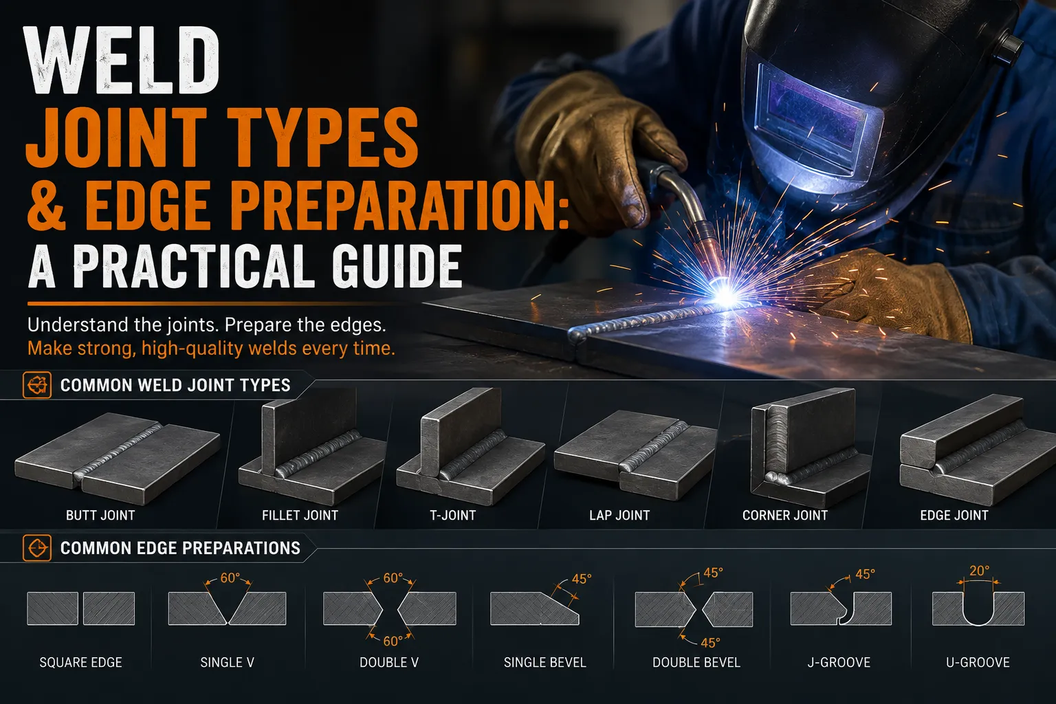
Most welded assemblies use one or more of five joint arrangements: butt, lap, tee, corner and edge.
Miller’s guide to the five basic weld joints emphasizes accurate fit-up and the use of fixtures to maintain alignment and control distortion.
1. Butt Joints
A butt joint places two components in approximately the same plane with their edges meeting. It is common in plate, sheet, pipe and fabricated panels.
Thin material may use a square butt joint with little or no bevel. As thickness increases, a groove is commonly prepared so the welding process can reach and fuse the root.
Common preparations include:
- square groove;
- single-V;
- double-V;
- single bevel;
- double bevel;
- U-groove; and
- J-groove.
A single-V is straightforward to cut but concentrates more weld metal and shrinkage on one side. A double-V can balance heat and reduce weld volume on thick material, but it requires access from both sides and additional handling.
2. Lap Joints
A lap joint overlaps two components. Fillet welds are commonly placed along one or both edges.
Lap joints are simple to assemble and useful for sheet and plate, but the overlap increases material use and can create a crevice where moisture collects. If the product will be exposed outdoors, consider drainage, sealing and corrosion protection.
Control overlap length, contact between surfaces and edge position. Large gaps between layers increase the chance of burn-through, poor fusion and distortion. Avoid welding directly over coatings or trapped contamination between plates.
3. Tee Joints
A tee joint places one member approximately perpendicular to another. Fillet welds are common on one or both sides.
The joint must provide correct angle, contact and access. A gap at the root can increase required weld metal and change the effective throat. In thick or highly loaded connections, groove preparation may be required rather than relying on a surface fillet.
Use a square or fixture to establish the angle. Anticipate angular distortion: a fillet on one side tends to pull the upright member toward the weld. Balanced welding can reduce that movement when the design permits.
4. Corner Joints
Corner joints connect components at their edges to form an L-shaped or box-like assembly. They are common in cabinets, tanks, trays and sheet-metal enclosures.
Configurations include open corner, closed corner and flush corner arrangements. The choice affects edge access, appearance, sealing and grinding.
Thin-sheet corners require accurate fit-up. A large gap can cause burn-through, while too much overlap can create an oversized seam and difficult finishing. If a corner must be watertight, the weld procedure and leak-testing method should be specified.
5. Edge Joints
An edge joint places parallel surfaces together and welds along their adjacent edges. It is used in sheet-metal flanges, stiffeners and some built-up sections.
Edge joints are not suitable for every loading direction because the effective fusion area may be limited. The designer should verify load transfer and service conditions. Thin edges can melt away quickly, so process and heat control matter.
Groove Preparation Terms
Understanding groove terminology prevents confusion between the drawing and workshop.
Bevel angle
The angle prepared on one component edge. Two opposing bevels combine to create the included groove angle.
Root face
The un-beveled land at the root. It helps control penetration and supports the molten pool.
Root opening
The gap between components at the root. It provides access for penetration but must remain consistent.
Groove angle
The included angle between prepared faces. A narrow angle reduces weld volume but may restrict torch or electrode access.
Root radius
The curved transition used in U- and J-grooves. These preparations can reduce weld volume on thick material but often require machining.
Backing
A material or component placed behind the joint to support the root. Backing may remain or be removed depending on the design and procedure.
Why Preparation Changes With Thickness
The arc must access and fuse the required depth. A square edge may be sufficient for thin sheet, while a thick plate needs a groove, higher-energy process or welding from both sides.
Increasing the groove angle improves access but also increases weld volume, filler cost, heat and distortion. Increasing the root gap can improve root penetration but raises burn-through risk and consumption. The preparation is therefore an engineered balance.
Never apply a single bevel standard to every material and process. Use the drawing, code or qualified WPS.
Cutting the Edge
Edges may be prepared by machining, sawing, grinding, oxy-fuel cutting, plasma, laser or waterjet. The method affects accuracy, oxide, hardness, dross and cleanup.
After thermal cutting, remove slag, heavy oxide and irregularities as required. Check plasma-cut edges intended for welding because air plasma can alter edge chemistry; Hypertherm notes that nitriding and oxidation can contribute to weld porosity and may require suitable cleanup or filler practice in its plasma gas selection guide.
Grinding must produce a smooth, consistent bevel without deep grooves. Avoid overheating the edge or reducing thickness below tolerance.
Material-Specific Preparation
Carbon steel
Remove oil, paint, moisture, loose rust, slag and heavy scale. Higher-strength or higher-carbon steels may require controlled thermal cutting, preheat and low-hydrogen practice.
Stainless steel
Use tools dedicated to stainless steel. Carbon-steel contamination can reduce corrosion resistance. Control grinding heat and remove contamination, adhesive and oxide as required.
Aluminium
Remove grease before oxide. Use an approved solvent and then a clean stainless brush dedicated to aluminium. Soft aluminium edges can smear during cutting, so use sharp tools and inspect the joint face.
Galvanized or coated steel
Identify the coating and follow the exposure-control plan. Remove coatings only as specified in the weld zone, provide effective fume extraction and restore corrosion protection after inspection.
Fit-Up Is Part of Joint Preparation
A correct bevel can still fail if fit-up is inconsistent. Check:
- root gap along the full length;
- high-low or edge misalignment;
- joint angle;
- straightness;
- contact at fillet roots;
- tack quality; and
- access for the welding gun or electrode.
Use spacers, bridges, clamps and fixtures that maintain the specified geometry. Do not force severely inaccurate parts together and expect the weld to correct them.
Tack Welding the Joint
Tacks must be compatible with the final procedure. Clean the tack area and use the correct filler. Place enough tacks to hold the root opening during welding.
Feather tack ends where required so the final pass fuses them completely. Remove cracked or porous tacks. On critical materials, tack welding may need the same preheat and shielding conditions as final welding.
Provide Access for Welding and Inspection
A joint may look acceptable in CAD but be impossible to weld once neighboring parts are installed. Review torch angle, nozzle size, electrode length, welder posture and visibility.
Also provide access for cleaning between passes and for required nondestructive testing. TWI notes that welded joint design must allow the specified inspection to be carried out, not only permit deposition of weld metal.
Control Weld Volume
More weld metal means more time, filler, heat and contraction. Use the specified preparation and weld size. Avoid widening a groove unnecessarily or filling poor fit-up with oversized beads.
For repeated products, measure actual filler consumption and distortion. That information can justify a revised joint design, double-sided preparation or more efficient process—subject to engineering approval.
Pre-Weld Joint Checklist
Before striking the arc, confirm:
- correct joint type and drawing revision;
- correct bevel, groove angle, root face and gap;
- correct material and thickness;
- edges free from unacceptable defects and contamination;
- fit-up within tolerance;
- tacks sound and correctly positioned;
- welding and inspection access available;
- correct filler, process and WPS selected; and
- preheat and interpass requirements understood.
Conclusion
Butt, lap, tee, corner and edge joints each offer different advantages and limitations. Their success depends on more than shape: bevel angle, root face, gap, edge condition, access, fit-up and sequence all affect the finished weld.
Prepare the joint from the drawing and qualified procedure. Accurate preparation gives the welder access to produce the required fusion with less filler, less distortion and fewer repairs.
 No products in the cart.